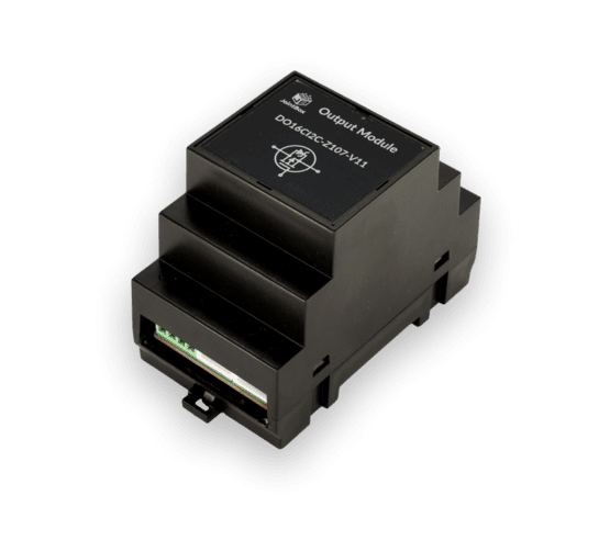
Output Module

Operation Principle
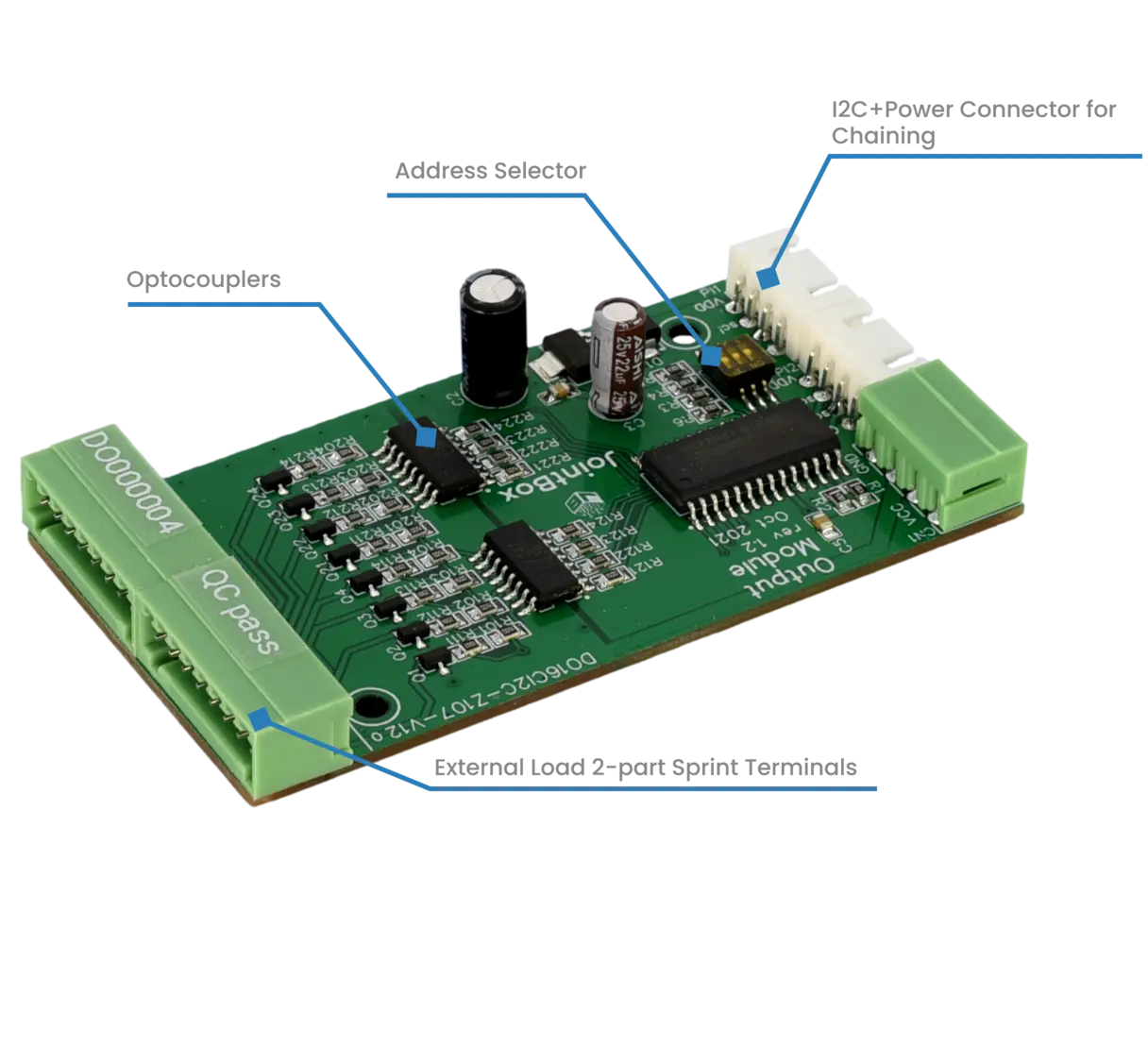
Output Module provides 16 independent channels operated from the Controller module. Each channel is connected to the load via optocoupler and transistor to ensure low output impedance and galvanic isolation.
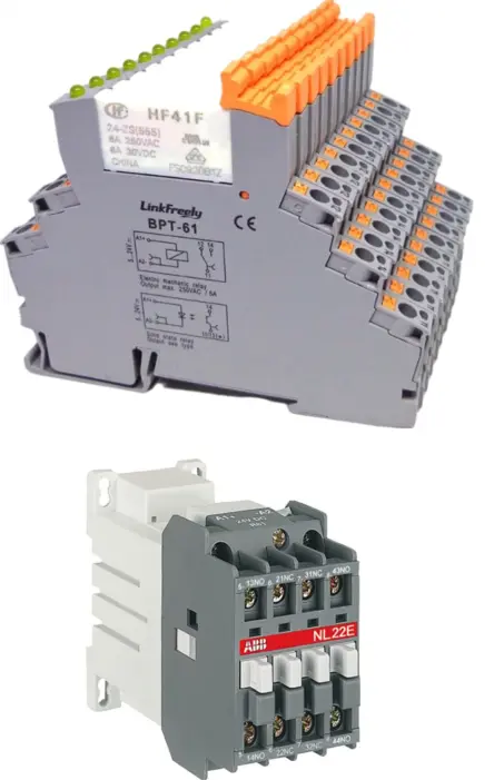
Channels can be connected to traditional relays, Solid State relays, and contactors to operate any load from heaters through lights to AC power motors. Output module provides separation of concerns - the actual relay device is selected basing on the load parameters and budget.
With ESPHome and Home Assistant integration the output channels can be directly controlled from Home Assistant interface, but can also be used in both local automation on single Controller module, or in higher-level automations in Home Assistant involving multiple smart devices.
Design Features
The output circuitry is disconnected from the module power: it uses different power line and the signal is galvanically decoupled from the digital part with optocouplers.
It is possible to connect total of 8 input and output modules total (for example, maximum of 3 output + 5 input). The I2C address selection is performed with a micro on-board switch. Thus, in total it is possible to connect 128 outputs to a single controller
Mix-and-match relay devices to your needs. Use approved, industrially produced load control devices depending on the application, whether this be powerful 63A contactor, or a tiny wafer-style modular relay.
Specifications
| Property | Description |
|---|---|
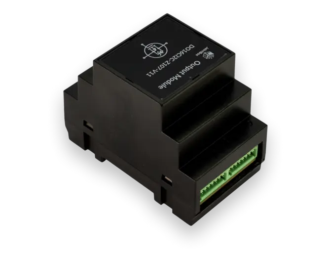
| Mount | DIN-rail mounted enclosure, 3-unit width (52.5mm) |
| Communication Interfaces | I2C |
| Chip | MCP23017 |
| Power | DC 12V separate line for the switching circuitry, 4-pole 2 poles as input and 2 as output to chain power line to further modules. |
| Interface Terminals | I2C+Power via standard JST 4-pole cable |
| Output Terminals | 2x 8-channel spring 2-part connectors for driving external relays. 12V relays should be used, with a control DC current of max 200ma per channel. |


