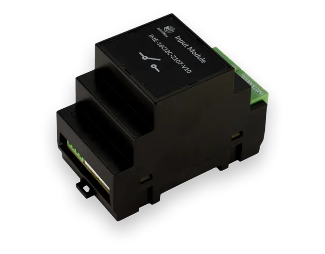
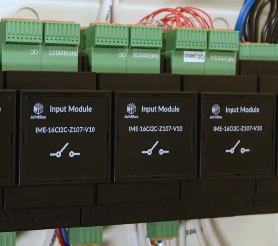
Input Module
Operation Principle
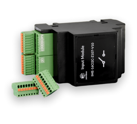
Input Module has 16 channels to connect to any type of binary input device: pushbuttons to emulate normal light switch behavior, limit switches to detect positions of moving parts, reed switches to detect door and window open/close state, or even simplistic pair of contacts to act as a water leak sensor.
For each channel, the Input module detects open or close state and sends it further to Controller. Then, the Controller can either run local automation (switch on the lights, ring an alarm etc), and also publish change further to HomeAssistant for higher-order automations.
Design Features
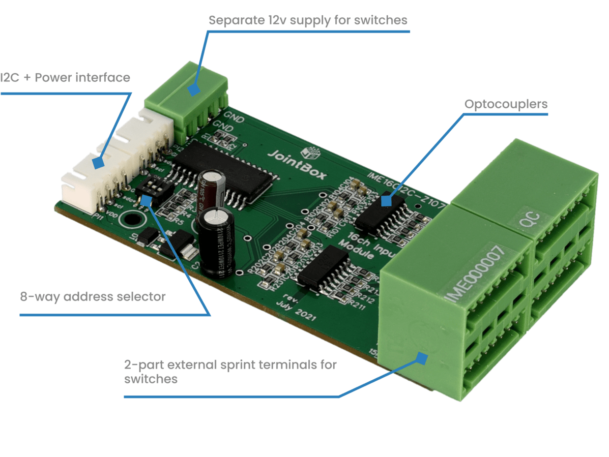
The input circuitry is disconnected from the module power: it uses different power line and the signal is galvanically decoupled from the digital part with optocouplers.
It is possible to connect total of 8 input and output modules by choosing different I2C addresses for each. For example, following modules can be connected: 3 output + 5 input or 4 outputs + 4 inputs. The I2C address selection is performed with a micro on-board switch.
Specifications
| Property | Description |
|---|---|
| Mount | DIN-rail mounted enclosure, 3-unit width (52.5mm) |
| Communication Interfaces | I2C |
| Chip | MCP23017 |
| Power | DC 12V separate line for the switching circuitry, 4-pole 2 poles as input and 2 as output to chain power line to further modules. |
| Interface Terminals | I2C+Power via standard JST 4-pole cable |
| Input Terminals | 2x 8-channel 2-row spring 2-part connectors for external switches and pushbuttons. Each button has its own pair of terminals so no need for chaining common. |
